Analog and Digital Signals
Students compare analog and digital representations of information and use evidence to explain why digitized signals are generally more reliable for transmitting information.

Illustrations are auto-generated and may be placeholders. They can be refreshed to match the narration.
Signals Carry Information
A signal is a changing quantity that carries information from a sender to a receiver. The change may be in sound pressure, electric voltage, light intensity, or radio-wave strength. A code gives those changes meaning. For example, a student can switch a flashlight on and off to send a message in Morse code. The light is the signal, while the agreed pattern tells the receiver which letters were sent. Signals can be stored as well as transmitted. A microphone converts sound into an electrical signal, and a speaker converts that signal back into sound. Analog signals represent information with continuous changes. Digital signals represent information using separate values, usually binary digits called bits. Both types can communicate the same message, but they respond differently to interference during transmission or copying.

How Analog Signals Work
An analog signal changes continuously, so every value within its range is possible. When a person speaks into a microphone, a thin part inside the microphone vibrates with the sound. The microphone produces a continuously changing voltage that follows the sound pattern. Louder sounds usually create larger changes, while pitch is related to how rapidly the pattern repeats. Traditional vinyl records provide a concrete example of analog storage. The record’s groove varies continuously, and a needle follows those variations to reproduce the sound. Small scratches, dust, or wear can add unwanted vibrations, so repeated playback may include pops or distortion. Analog technology can represent smooth detail very well, but any unwanted change becomes part of the signal unless it is removed by special equipment.

How Digital Signals Work
A digital system represents information with a limited set of separate values. Most digital devices use binary code, in which 0 and 1 are represented by two voltage ranges. To digitize sound, a device measures, or samples, an analog signal at regular times. Each measurement is rounded to an allowed numerical level and stored as a sequence of bits. For example, a phone converts a voice into digital data before sending it. The receiving phone reads the bits and uses them to produce an approximate version of the original sound. More frequent samples and more available numerical levels can preserve greater detail, although they require more data. Digital signals are not automatically perfect, but their distinct values make them easier to identify, copy, and restore during transmission.

Noise and Signal Quality
Noise is any unwanted disturbance that changes a signal. It can come from electrical equipment, weather, obstacles, weak connections, or damage to a storage medium. If noise is added to an analog signal, the receiver usually cannot tell exactly which small variations were original and which came from interference. The noise may remain as static or distortion. A digital receiver instead checks whether each received value is closer to the range for 0 or the range for 1. If the disturbance is not too large, the receiver can recover the intended bit. A repeater can then create a clean new digital pulse before sending it onward. For example, a slightly weakened digital pulse can still be read correctly as 1. However, strong noise can cross the decision threshold and cause an incorrect bit.

Comparing Transmission Reliability
Reliability can be tested by sending the same information through several noisy links and comparing the final output with the original. Imagine transmitting a picture through five relay stations. At each analog relay, small errors in brightness and color may be copied along with the picture, so the errors can accumulate. Digital stations read the bits and regenerate standard 0 and 1 signals. If each bit remains recognizable, the final digital picture matches the original data. Evidence from such experiments or simulations supports the conclusion that digital transmission is generally more reliable. The comparison must use similar distances and noise levels to be fair. Historically, communication systems shifted from analog telephone, radio, and television equipment toward digital networks. The purpose of sharing voices and images continued, while the methods of encoding, copying, correcting, and storing information changed.

Evidence-Based Claim
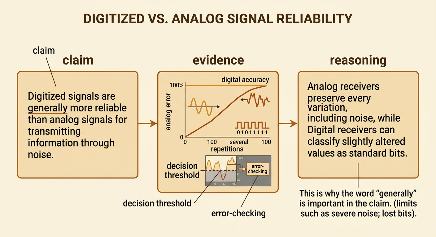
A strong scientific explanation includes a claim, evidence, and reasoning. One supported claim is: Digitized signals are generally more reliable than analog signals for transmitting information through noise. Evidence might include a classroom test in which an analog waveform changed after several noisy copies, while a digital bit pattern remained unchanged after being regenerated. A technical reading or simulation may provide additional evidence showing how decision thresholds and error-checking methods help receivers recover data. The reasoning connects the evidence to the claim: analog receivers preserve every variation, including noise, but digital receivers can classify slightly altered values as standard bits. The word generally is important because severe interference, poor sampling, or lost bits can still damage digital information. Comparing experimental results, technical explanations, and historical communication examples produces a more complete and defensible conclusion than relying on one source alone.