Designing and Testing Finite-State Machines
Students model the behavior of a digital system as a finite-state machine, implement its transitions, and test edge cases against stated requirements.
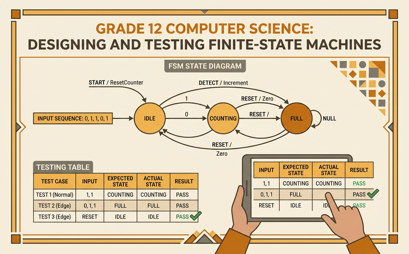
Illustrations are auto-generated and may be placeholders. They can be refreshed to match the narration.
States, Inputs, and Transitions
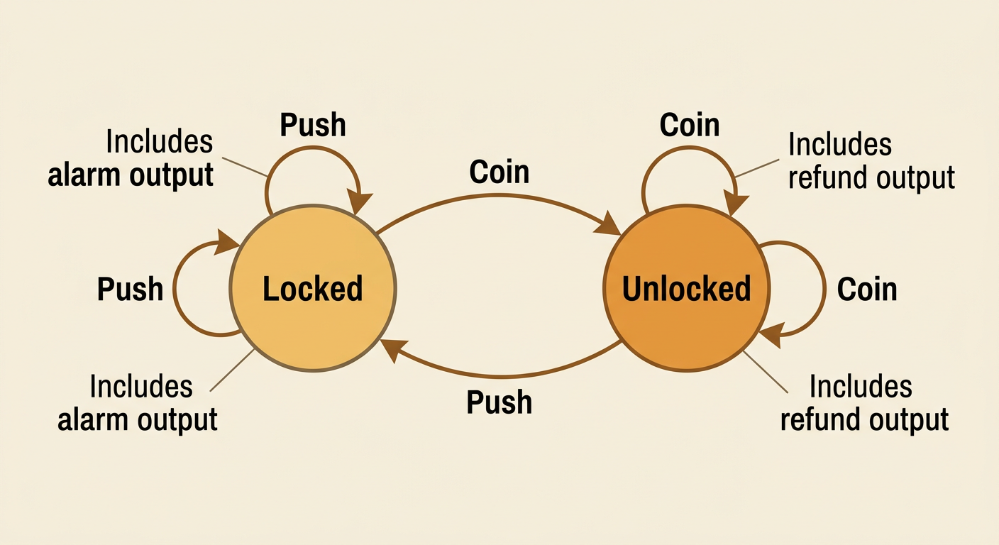
A finite-state machine models a system using a limited set of states, possible inputs, and rules called transitions. A state records the system’s current condition. An input is an event or signal that may cause the condition to change. A transition identifies the next state for each combination of current state and input. Consider a subway turnstile with two states: Locked and Unlocked. If the turnstile is Locked and receives a coin, it transitions to Unlocked. If a rider pushes while it is Unlocked, it returns to Locked after the rider passes. Some inputs do not change the state. For example, pushing a Locked turnstile keeps it Locked and may activate an alarm. Because the next action depends on both the current state and the input, the machine must store its state between events.
Translating Requirements into a State Diagram
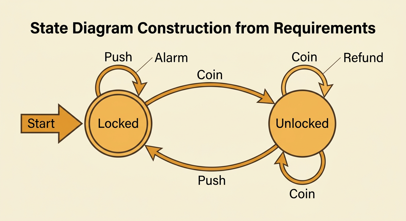
Begin by rewriting each requirement as a precise rule with a current state, an input, a next state, and any output. Suppose the requirements say that the turnstile starts Locked, a coin unlocks it, one push through relocks it, pushing while Locked triggers an alarm, and inserting a coin while Unlocked returns the coin. Draw one circle for each state and mark Locked as the initial state. Then draw a directed arrow for every rule. Label each arrow with the input and, when needed, the output. The rule “If the machine is Locked and a rider inserts a coin, unlock it” becomes an arrow from Locked to Unlocked labeled “Coin.” Check that every stated input has an outgoing transition from every state. This process decomposes a paragraph of requirements into smaller rules that can be reviewed for omissions or contradictions.
Building a Transition Table
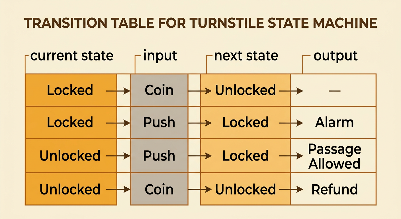
A transition table lists the same rules as a state diagram in a form that is easy to verify and implement. Create one row for every combination of current state and valid input. Include columns for current state, input, next state, and output. For the turnstile, the row Locked plus Coin gives Unlocked with no special output. Locked plus Push gives Locked with Alarm. Unlocked plus Push gives Locked with Passage Allowed, while Unlocked plus Coin gives Unlocked with Refund. A complete table prevents programmers from overlooking a case. With two states and two valid inputs, the basic table needs four rows. If a row is missing, the behavior is undefined for that situation. Review the table against the original requirements in sequence, and confirm that each rule appears exactly once without conflicting next states or outputs.
Implementing the State Machine
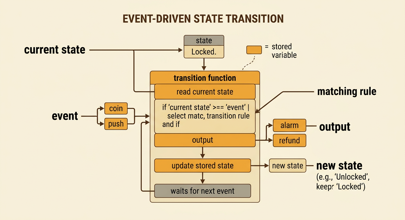
An implementation stores the current state in a variable and processes one input event at a time. Initialize the turnstile’s state as Locked. When an event arrives, select the rule that matches both the stored state and the event. If the state is Locked and the input is Coin, assign Unlocked as the new state. If the state is Locked and the input is Push, keep the state Locked and activate the alarm. Similar branches handle inputs while Unlocked. Update the state only after the matching rule has been identified, because changing it too early can cause the program to evaluate the wrong branch. Outputs such as Alarm or Refund should be produced as specified but should not change the state unless a transition rule says so. Keeping transition logic in one function makes the behavior easier to inspect, reuse, and test.
Testing Invalid Inputs and Edge Cases
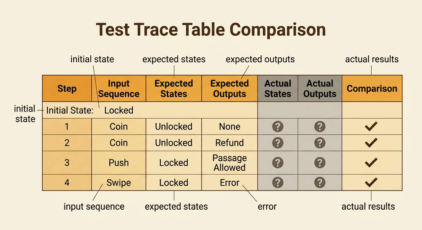
Testing should cover every transition, repeated events, invalid inputs, and boundary timing. Create a test with an initial state, an input sequence, expected states, and expected outputs. For example, starting Locked and processing Coin, Coin, Push should produce Unlocked, Unlocked, Locked, with a Refund after the second coin. Also test Push while Locked and confirm that the state remains Locked while the alarm activates. Invalid data, such as an unknown event named Swipe, should follow a stated policy: reject the event, record an error, and preserve the current state. Edge cases include an empty input sequence, many repeated coins, rapid pushes, and two events reported at the same time. If simultaneous events are possible, requirements must define their priority or ordering. Compare actual results with expected results, document failures, and explain which requirement or transition must be corrected.