
Electric Potential and DC Circuits
Students relate voltage, current, resistance, and electrical power while analyzing series and parallel direct-current circuits.
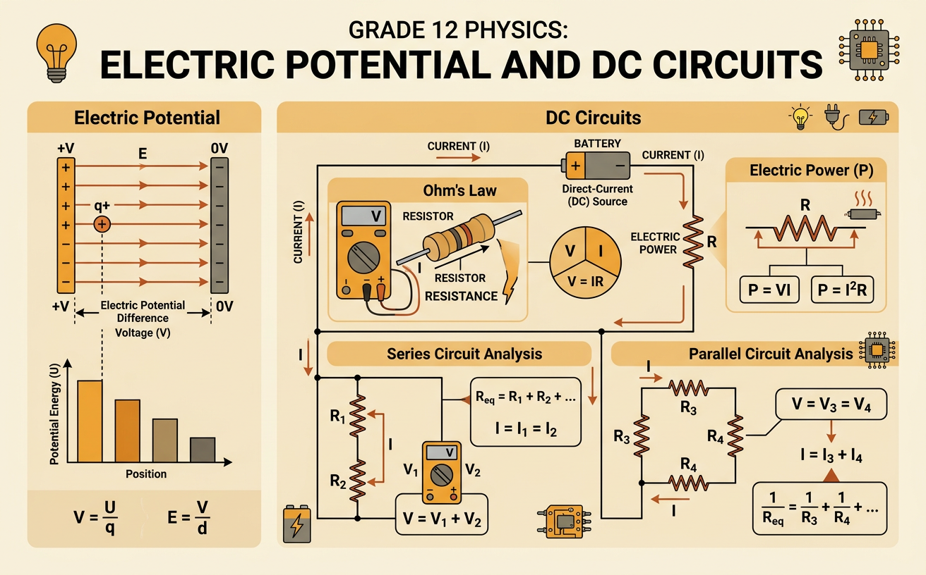
Illustrations are auto-generated and may be placeholders. They can be refreshed to match the narration.
Charge Flow and Current
Electric current describes the rate at which electric charge passes a point in a circuit. It is calculated with I = Q/t, where I is current, Q is charge, and t is time. One ampere equals one coulomb of charge per second. In metal wires, negatively charged electrons move from the negative terminal toward the positive terminal. By convention, however, current is shown in the opposite direction, from positive to negative. A steady current requires a closed conducting path. For example, if 12 coulombs of charge pass through a wire in 3 seconds, the current is I = 12 C/3 s = 4 A. Opening a switch breaks the path, so charge no longer flows continuously and the current becomes zero.
Electric Potential Difference
Electric potential difference, commonly called voltage, is the change in electric potential energy per unit charge. It is expressed as V = ΔU/q, and one volt equals one joule per coulomb. A battery creates a potential difference by using chemical energy to separate charges. When charges move through a circuit component, their electric potential energy may be converted into light, thermal energy, or motion. For example, a 9 V battery transfers 9 joules of energy to or from each coulomb of charge that moves through the complete circuit. If 2 C of charge pass through a device connected across the battery, the energy transferred is ΔU = Vq = (9 V)(2 C) = 18 J. Voltage is measured with a voltmeter connected in parallel across the component being tested.
Resistance and Ohm’s Law
Resistance measures how strongly a component opposes electric current. Its SI unit is the ohm, represented by Ω. For many conductors at constant temperature, voltage, current, and resistance follow Ohm’s law: V = IR. Increasing the voltage across a fixed resistance increases the current proportionally, while increasing resistance at a fixed voltage decreases the current. For example, a 6 Ω resistor connected across a 12 V source carries I = V/R = 12 V/6 Ω = 2 A. An ammeter measures current and must be placed in series with the resistor. On a graph of voltage versus current for an ohmic resistor, the data form a straight line through the origin. The slope V/I equals the resistance, so a steeper line represents a larger resistance.
Series Circuits
In a series circuit, components are connected along one continuous path. Because charge has no alternate route, the current is the same through every component. The source voltage equals the sum of the potential differences across the components, and the equivalent resistance is Rₑq = R₁ + R₂ + ⋯. Adding another series resistor therefore increases total resistance and decreases the circuit current if the source voltage remains constant. For example, a 2 Ω resistor and a 4 Ω resistor connected in series to a 12 V battery have an equivalent resistance of 6 Ω. The current is I = 12 V/6 Ω = 2 A everywhere. The voltage drops are 4 V across the 2 Ω resistor and 8 V across the 4 Ω resistor, which add to the battery’s 12 V.
Parallel Circuits
In a parallel circuit, components are connected on separate branches between the same two junctions. Each branch has the same potential difference as the source, but the current can differ among branches. At a junction, the total current equals the sum of the branch currents because charge is conserved. Equivalent resistance is found using 1/Rₑq = 1/R₁ + 1/R₂ + ⋯, so it is always less than the smallest branch resistance. For example, connect 6 Ω and 3 Ω resistors in parallel across a 12 V battery. The branch currents are 12 V/6 Ω = 2 A and 12 V/3 Ω = 4 A. The source supplies 6 A total, and the equivalent resistance is Rₑq = 12 V/6 A = 2 Ω. Adding parallel branches decreases equivalent resistance and increases total current.
Electrical Power
Electrical power is the rate at which a circuit transfers electrical energy. It is measured in watts, where one watt equals one joule per second. Power can be calculated with P = IV. For an ohmic resistor, substituting Ohm’s law gives P = I²R or P = V²/R. The appropriate form depends on which quantities are known. For example, a resistive device operating from a 120 V DC source with a current of 0.50 A uses P = (120 V)(0.50 A) = 60 W. Its resistance is R = V/I = 240 Ω. If it operates for 50 minutes, or 3,000 seconds, it transfers E = Pt = (60 W)(3,000 s) = 180,000 J of energy. Greater power means energy is transferred more rapidly, not that a device necessarily operates for a longer time.