Electromagnetic Induction: From Motion to Electric Power
Students model how changing magnetic flux induces current and apply this principle to generators, transformers, and decisions about electric-grid infrastructure.
Illustrations are auto-generated and may be placeholders. They can be refreshed to match the narration.
Magnetic Flux and Changing Fields
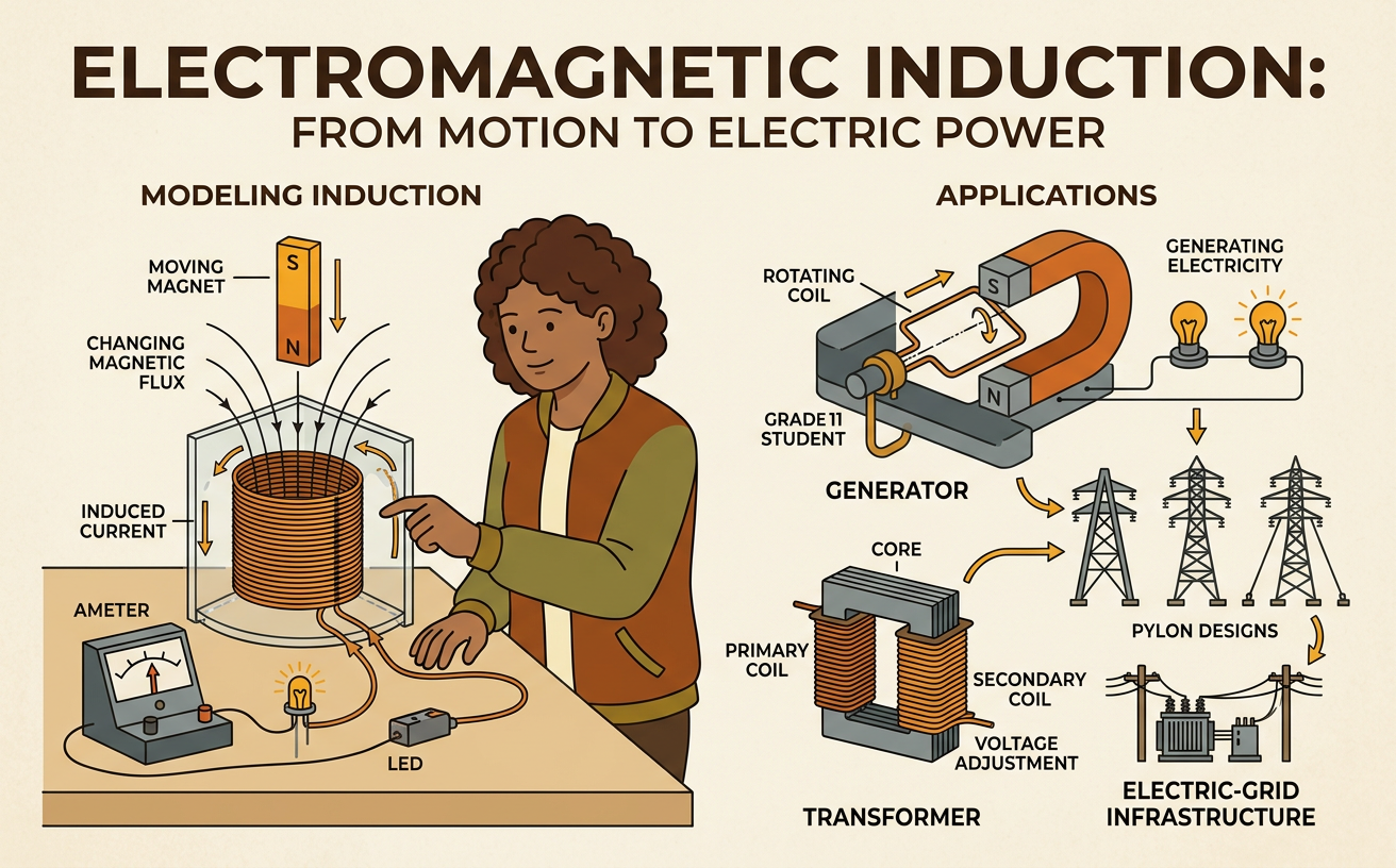
Magnetic flux measures how much magnetic field passes through a surface. For a uniform field and flat loop, flux depends on field strength, loop area, and orientation: flux equals B times A times the cosine of the angle between the field and the line perpendicular to the loop. Flux changes if the magnetic field changes, the loop’s area changes, or the loop rotates. A changing flux can induce a voltage and, in a closed circuit, a current. For example, pushing a bar magnet toward a wire loop increases the magnetic flux through the loop. Holding the magnet still produces no continuing induced current, even if the magnetic field is strong. Pulling the magnet away changes the flux in the opposite direction, so the induced current reverses.

Observing Induced Current
To observe induction, connect a coil of insulated wire to a sensitive galvanometer. Record the needle’s starting position, then move a bar magnet into the coil at a steady speed and note the direction and size of the deflection. Hold the magnet still, withdraw it, and repeat each trial at different speeds while keeping the magnet, coil, and motion distance constant. Faster motion should cause a larger deflection because the flux changes more rapidly. Reversing the motion or magnet pole should reverse the current. As a related test, connect the coil briefly to a battery and place a compass nearby. The compass turns while current flows, providing evidence that electric current produces a magnetic field. Follow the procedure precisely, disconnect the battery between trials, and record results in a data table.

Faraday’s and Lenz’s Laws
Faraday’s law states that the induced voltage equals the negative rate of change of magnetic flux multiplied by the number of coil turns. A larger number of turns or a faster flux change produces a greater induced voltage. The negative sign represents Lenz’s law: the induced current creates a magnetic field that opposes the change in flux. Suppose a magnet’s north pole approaches a coil. The increasing flux causes the near face of the coil to act like a north pole, resisting the approach. When the magnet moves away, the coil’s current reverses so the near face acts like a south pole, resisting the separation. This opposition does not stop motion automatically. Instead, an external force must do work, and that transferred energy can become electrical energy and thermal energy in the circuit.

Generators and Transformers
A generator converts mechanical energy into electrical energy by rotating a coil in a magnetic field, continually changing the flux through the coil. For example, steam in a power plant can spin a turbine connected to a generator shaft, producing alternating current. A transformer changes alternating voltage using two coils wrapped around a shared iron core. Alternating current in the primary coil creates a changing magnetic field, which induces voltage in the secondary coil. The voltage ratio approximately equals the turns ratio: a secondary coil with ten times as many turns produces about ten times the voltage. A step-up transformer raises voltage for transmission, while a step-down transformer lowers it for homes and devices. Transformers require changing current; steady direct current does not provide continuous flux change and therefore does not produce a continuous secondary voltage.

Electric-Grid Benefits and Tradeoffs
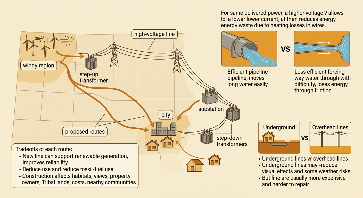
Electric grids use step-up transformers to transmit power at high voltage and low current. For the same delivered power, lower current reduces heating losses in transmission lines, so electricity can travel farther efficiently. Step-down transformers then provide safer, useful voltages near customers. Grid policies still involve tradeoffs. A proposed high-voltage line connecting a windy region to a city may improve reliability, reduce fossil-fuel use, and support renewable generation. However, it may also affect habitats, views, property owners, Tribal lands, construction costs, and nearby communities. Students can evaluate the policy by comparing routes, underground and overhead designs, costs, energy losses, outage risks, and public comments. A strong recommendation identifies intended outcomes, examines unintended consequences, cites evidence, and explains who receives the benefits and who bears the burdens.