
Engineering Safer Collisions with Newton’s Third Law
Students analyze action-reaction force pairs and collision data to explain how safety features reduce the effects of impacts.

Illustrations are auto-generated and may be placeholders. They can be refreshed to match the narration.
Observing a Collision
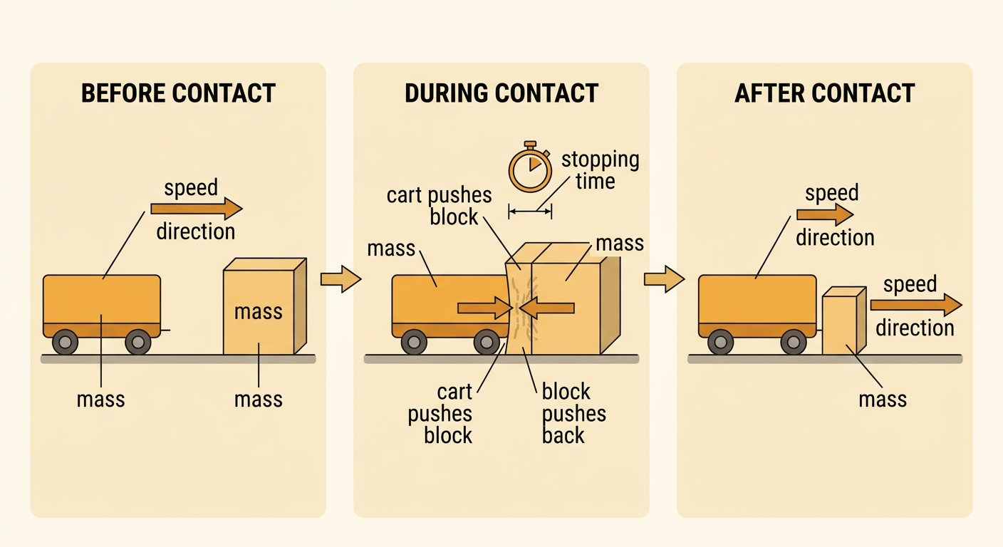
A collision occurs when two objects touch and exert forces on each other for a short time. Imagine a rolling cart hitting a stationary foam block. During contact, the cart may slow down while the block begins moving. Careful observations should describe changes in motion before, during, and after the impact. Useful measurements include each object’s mass, speed, direction, and stopping time. The cart and block do not need to have the same change in motion. A lighter object can have a greater change in speed than a heavier object even though both experience interaction forces. Engineers study these changes to identify collision problems, such as a passenger stopping too suddenly. They then design features that control how objects move and deform during an impact.
Newton’s Third Law Force Pairs
Newton’s Third Law states that when one object exerts a force on a second object, the second object exerts an equal-strength force in the opposite direction on the first. If cart A rolls right and strikes cart B, cart A pushes cart B to the right. At the same time, cart B pushes cart A to the left with an equally strong force. These forces form an action-reaction pair. They do not cancel because they act on different objects. The carts may still have different changes in speed if their masses differ. For example, when a heavy truck collides with a small car, each exerts an equal and opposite force on the other, but the lower-mass car usually has a greater change in velocity. Force arrows should be equal in length and point in opposite directions.

Comparing Impact Data
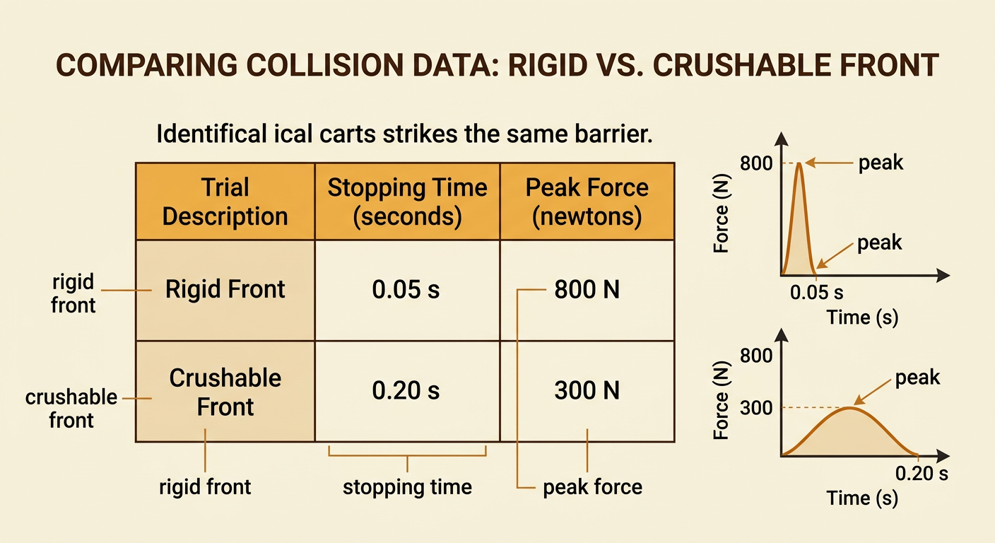
Collision data can show how a safety feature changes an impact. Suppose the same test cart hits a barrier at 4 meters per second in two trials. With a rigid front, the cart stops in 0.05 second and reaches a peak force of 800 newtons. With a crushable front, it stops in 0.20 second and reaches a peak force of 300 newtons. In both trials, the cart changes from the same starting speed to rest, but the crushable front increases the stopping time and lowers the peak force. The barrier still pushes on the cart with a force equal and opposite to the cart’s force on the barrier. When comparing tests, engineers keep mass and starting speed constant so the evidence supports a fair conclusion. They also repeat trials because one result may be affected by measurement error.
Designing a Safety Feature
An engineering design should address clear criteria and constraints. Consider designing a bumper for a model car carrying a raw egg as a passenger. The criterion could be that the egg must remain unbroken when the car hits a wall at a set speed. Constraints might limit the bumper to 20 grams of cardboard, foam, and tape and require it to fit within 8 centimeters of the car’s front. A layered, crushable bumper can deform during the collision, increasing the time over which the car and egg slow down. This can reduce the peak force on the egg. Newton’s Third Law still applies: the wall and car exert equal and opposite forces on each other. Students should build, test, measure, and revise the design rather than assume the first idea will work. A successful design meets the criterion without violating the constraints.

Supporting a Design with Evidence
A strong design explanation makes a claim, cites specific evidence, and connects that evidence to scientific reasoning. For example, a student might claim that a layered foam bumper is safer than a rigid cardboard bumper. The student can cite test results: at the same cart mass and starting speed, the foam bumper increased stopping time from 0.06 second to 0.18 second and reduced peak force from 700 newtons to 350 newtons. The reasoning is that deformation increases stopping time, reducing the peak force experienced by the cart and passenger. The explanation should also acknowledge strengths and weaknesses. A strength is that the tests used equal speeds and repeated trials. A weakness is that a model car and egg do not represent every part of a real vehicle or human body. Relevant data support the design, but limitations show what should be tested next.
