From Analog Signals to Binary Data
Students explore how computers encode text and images with binary digits and compare the reliability of digital information with analog signals.

Illustrations are auto-generated and may be placeholders. They can be refreshed to match the narration.
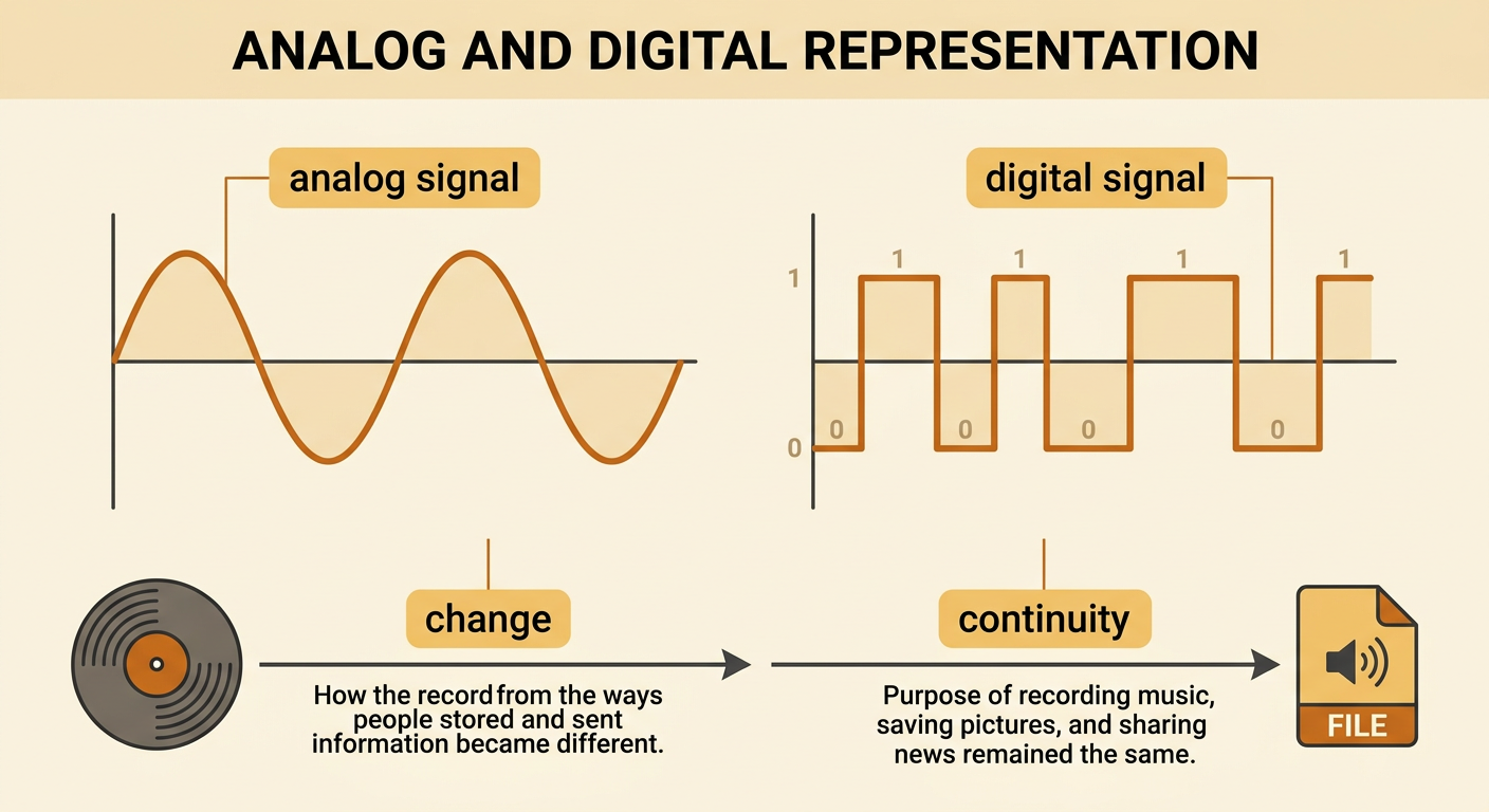
Analog and Digital Information
Information can be represented in analog or digital form. An analog signal changes continuously and can have any value within a range. For example, the groove of a vinyl record varies continuously to represent sound vibrations. A digital signal uses separate, fixed values. Computers usually represent these values with 0s and 1s. During the twentieth century, many technologies shifted from analog records, film cameras, and broadcast television to digital music, digital cameras, and streaming video. This transition shows change because the storage and transmission methods became different. It also shows continuity because people still recorded music, saved pictures, and shared news. The information and purposes continued even as the technology used to encode them changed.
Bits and Binary Patterns
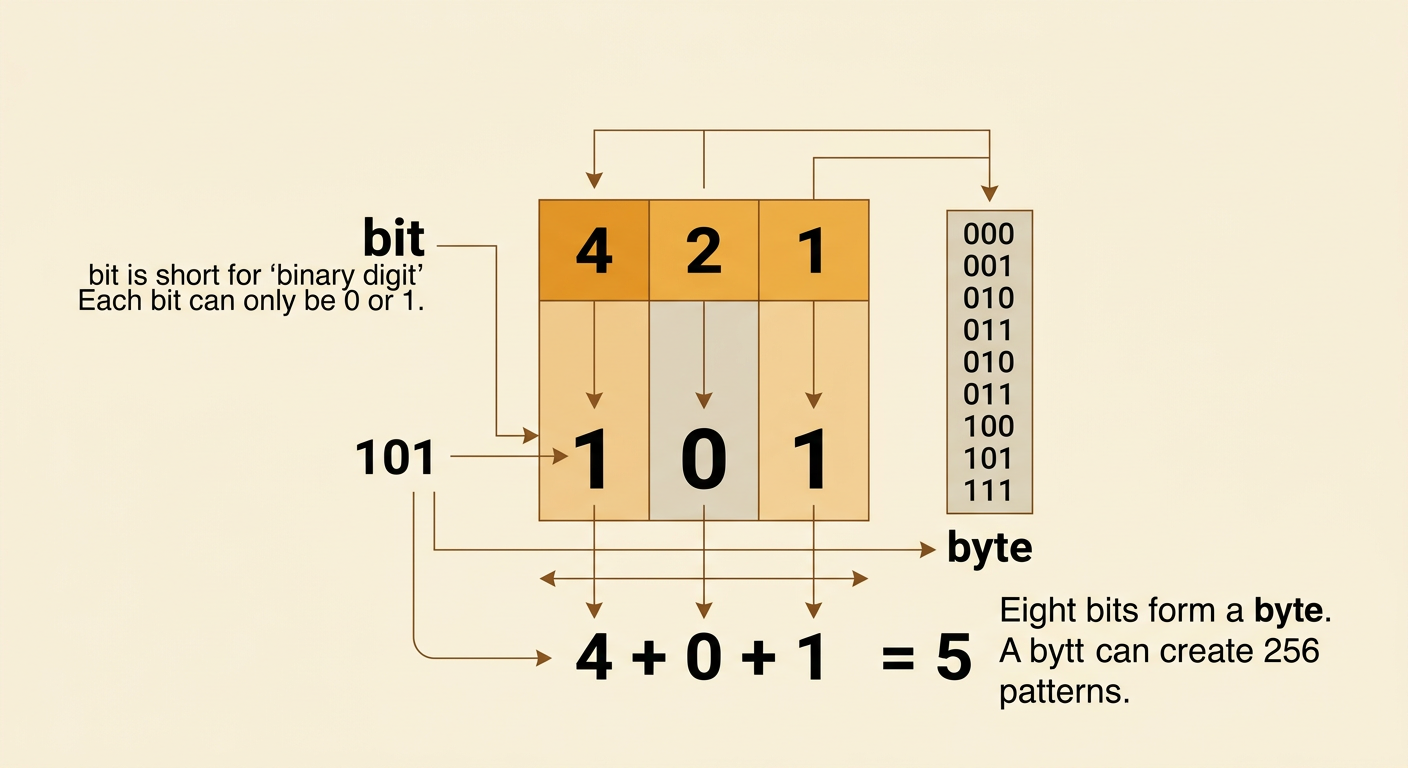
A bit, short for binary digit, is the smallest unit of digital data. Each bit has one of two values: 0 or 1. Computers combine bits into patterns that can represent numbers, letters, colors, sounds, and instructions. In a three-bit number, the positions represent 4, 2, and 1. The pattern 101 means one 4, zero 2s, and one 1, so it represents the decimal number 5. More bits allow more possible patterns. One bit makes 2 patterns, while three bits make 8 patterns, from 000 through 111. Eight bits form a byte and can create 256 different patterns. The meaning of a pattern depends on the encoding rule being used.
Encoding Text and Images
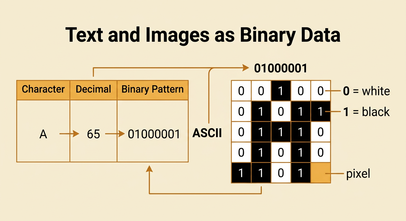
Computers use agreed-upon codes to connect binary patterns with text and images. In ASCII, one common text-encoding system, uppercase A has the decimal value 65 and the eight-bit pattern 01000001. A computer stores the pattern, while software interprets it as the letter A. Digital images are made of tiny picture elements called pixels. In a simple black-and-white image, each pixel can use one bit: 0 for white and 1 for black. For example, a 5-by-5 grid can display a block letter by placing black pixels where the pattern contains 1s. Color images need more bits per pixel to represent many colors. Text and images therefore look different to people, but both are stored as organized binary data.
Comparing Signal Reliability
Signals can be changed by noise, such as electrical interference or a weak connection. In an analog signal, even a small disturbance changes the signal’s exact shape. If the signal is copied repeatedly, these changes may build up and reduce quality. A digital receiver usually decides whether each signal level represents 0 or 1. If noise changes a pulse only slightly, the receiver can still identify the intended bit and rebuild a clean signal. For example, a slightly weakened high pulse can still be read as 1 if it remains above the decision threshold. This makes digitized signals generally more reliable for copying and transmission. Digital communication is not perfect: severe noise can push a pulse across the threshold and cause an error. Error-checking methods can help detect or correct such mistakes.

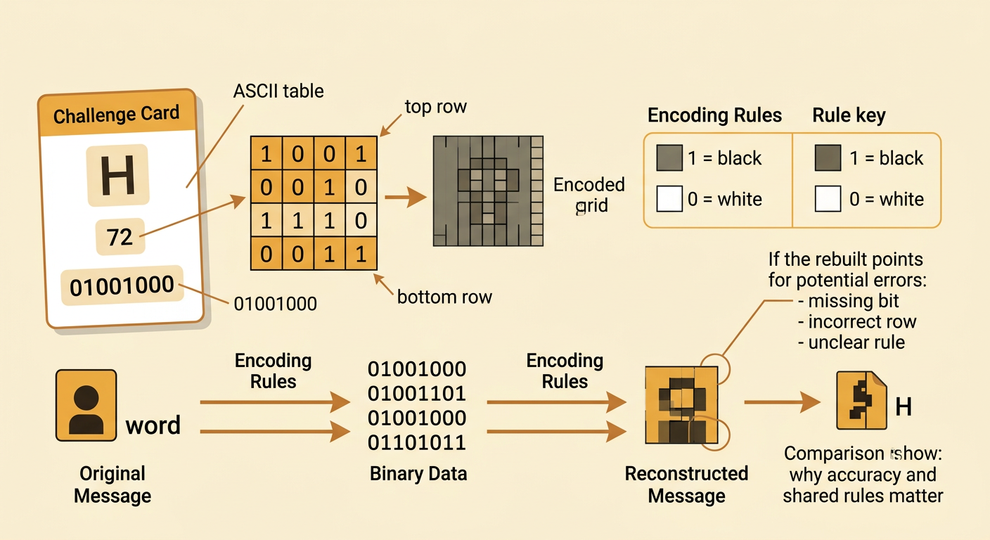
Binary Encoding Challenge
Use encoding rules to create and interpret a short digital message. First, write the eight-bit code for each letter in a two- or three-letter word using a provided ASCII table. For example, uppercase H is 72 in decimal, or 01001000 in binary. Next, design a 4-by-4 black-and-white icon. Write 1 for every black pixel and 0 for every white pixel, reading each row from left to right and moving from the top row to the bottom row. Exchange only the binary data and the encoding rules with a partner. Your partner should decode the letters and shade the pixel grid to rebuild the icon. Compare the result with the original. If they differ, check for a missing bit, an incorrect row, or a rule that was not clearly stated.