Ohm’s Law and Electric Power in DC Circuits
Students use circuit diagrams, measurements, and algebraic relationships to calculate resistance, current, voltage, power, and electrical energy in simple DC circuits.
Illustrations are auto-generated and may be placeholders. They can be refreshed to match the narration.
Circuit Quantities and Units
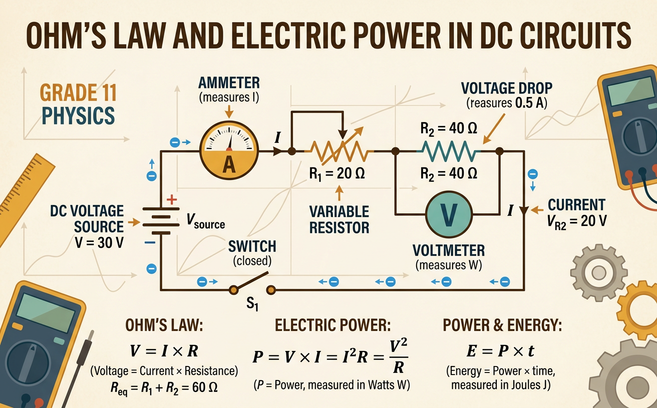
In a direct-current circuit, charge moves in one consistent direction around a closed path. Current, measured in amperes (A), is the rate at which charge flows. Voltage, measured in volts (V), is the electric potential difference that transfers energy to or from each coulomb of charge. Resistance, measured in ohms (Ω), describes how strongly a component opposes current. A battery supplies voltage, while a resistor converts electrical energy mainly into thermal energy. An ammeter is connected in series so the circuit’s current passes through it. A voltmeter is connected in parallel across a component. For example, if an ammeter reads 0.50 A and a voltmeter across a resistor reads 6.0 V, those measurements can be used to determine the resistor’s resistance.

Applying Ohm’s Law
Ohm’s law describes the relationship among voltage, current, and resistance for an ohmic component at a constant temperature: V = IR. Increasing the voltage across a fixed resistance increases the current in direct proportion. Increasing resistance while keeping voltage constant decreases the current. Suppose a 12 V battery is connected across a 4.0 Ω resistor. Substitute the known values into 12 V = I(4.0 Ω), then divide by 4.0 Ω to find I = 3.0 A. This result predicts the current in an ideal circuit. Measurements may differ slightly because real batteries have internal resistance, connecting wires are not perfect, and a resistor’s value can change as it heats. A graph of voltage versus current for an ohmic resistor is a straight line whose slope equals resistance.

Rearranging Circuit Equations
Circuit formulas can be rearranged to highlight the unknown quantity. Starting with Ohm’s law, V = IR, divide both sides by R to isolate current: I = V/R. Divide both sides by I to isolate resistance: R = V/I. Units help verify that the rearrangement makes sense because volts divided by ohms equals amperes, and volts divided by amperes equals ohms. For example, a device has 9.0 V across it and carries 0.30 A. Use R = V/I to calculate R = 9.0 V/0.30 A = 30 Ω. Before calculating, identify the requested variable, select an equation containing that variable, rearrange symbolically, and then substitute numbers. This approach reduces algebra errors and can be used with power and energy equations as well.

Calculating Electric Power and Energy
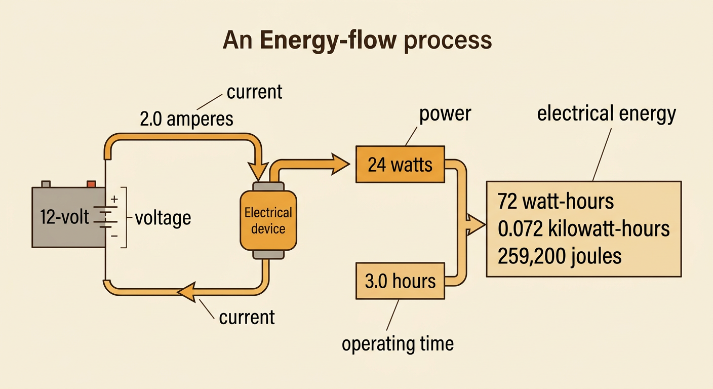
Electric power is the rate at which electrical energy is transferred. It is measured in watts, where one watt equals one joule per second. For a DC circuit, P = VI. Combining this equation with Ohm’s law also gives P = I²R and P = V²/R. Electrical energy is calculated with E = Pt. If a 12 V device draws 2.0 A, its power is P = (12 V)(2.0 A) = 24 W. If it operates for 3.0 hours, it uses 72 watt-hours, or 0.072 kilowatt-hours. In joules, the same energy is (24 J/s)(10,800 s) = 259,200 J. These equations form a computational model: changing voltage, current, resistance, or operating time changes the amount of energy transferred by a circuit component.
Connecting Power Use to Costs and Choices
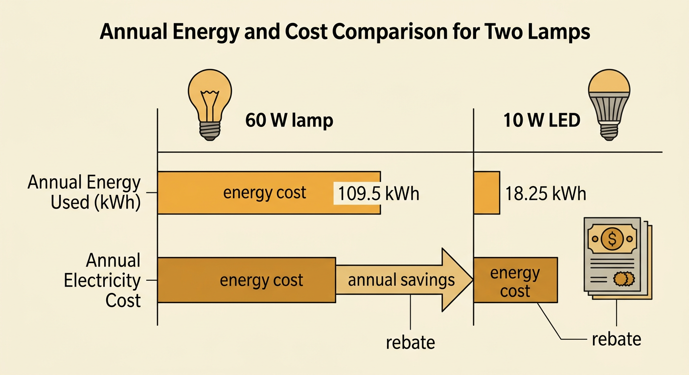
Utilities commonly bill electrical energy in kilowatt-hours rather than joules. Cost can be modeled as cost = energy used × price per kilowatt-hour. Consider a 60 W lamp and a 10 W LED that provide similar light for 5 hours each day. Over 365 days, the 60 W lamp uses 109.5 kWh, while the LED uses 18.25 kWh. At $0.15 per kilowatt-hour, the LED saves about $13.69 each year. A buyer must compare this operating savings with the LED’s purchase price and expected lifetime. Incentives such as rebates can encourage efficient choices by lowering the initial cost. However, policies may affect groups differently: customers may save on bills, retailers may change inventory, utilities may sell less energy, and taxpayers or ratepayers may fund rebates. Evaluating a policy requires considering both measurable energy savings and how its costs and benefits are distributed.