Reflection and Refraction of Light
Students use ray diagrams, the law of reflection, and Snell’s law to predict how light behaves at boundaries and explain applications such as lenses and fiber-optic communication.

Illustrations are auto-generated and may be placeholders. They can be refreshed to match the narration.
Light at a Boundary
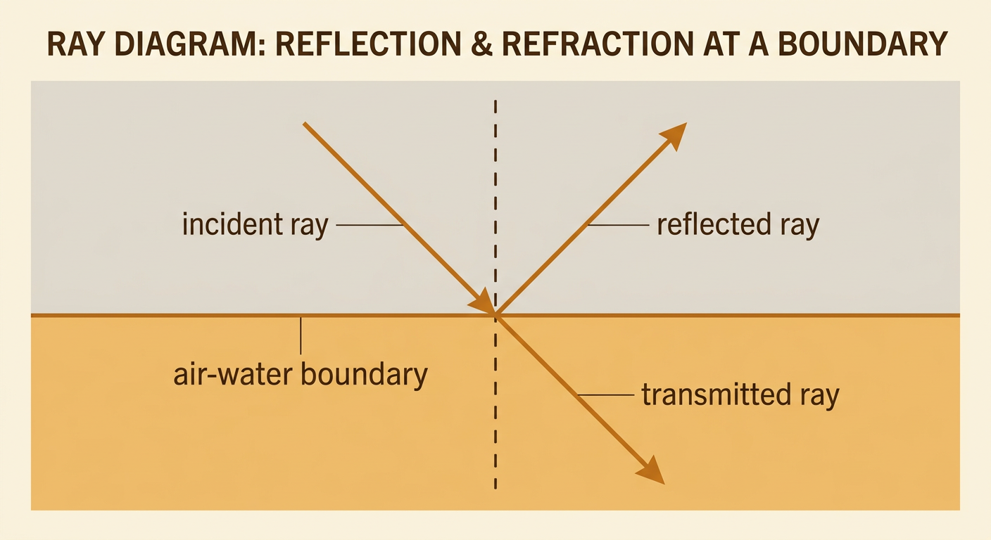
When light reaches a boundary between two materials, it may be reflected, transmitted, refracted, or absorbed. The outcome depends on the materials, the surface, and the angle at which the light arrives. A smooth air-glass boundary reflects some light and transmits the rest. The transmitted light usually changes direction because its speed changes in the new material. In contrast, a dark, rough surface may absorb much of the light and scatter the reflected portion in many directions. For example, sunlight striking a calm lake can produce a clear reflection while also entering the water and illuminating objects below. Ray diagrams represent light with straight arrows called rays. At a boundary, these rays help track the direction and relative behavior of the incident, reflected, and transmitted light.
The Law of Reflection
The law of reflection states that the angle of incidence equals the angle of reflection. Both angles are measured from the normal, an imaginary line perpendicular to the reflecting surface at the point where the ray strikes. They are not measured from the surface itself. The incident ray, reflected ray, and normal lie in the same plane. For example, if a laser beam strikes a plane mirror at an angle of 35 degrees from the normal, it reflects at 35 degrees on the opposite side of the normal. Reversing the direction of the light produces the same path, demonstrating that light paths are reversible. On a smooth mirror, parallel incoming rays remain organized after reflection. A rough surface still obeys the law at each point, but changing surface orientations scatter the rays.

Refraction and Refractive Index
Refraction is the change in a light ray’s direction when it crosses a boundary and its speed changes. A material’s refractive index is defined by n = c divided by v, where c is the speed of light in a vacuum and v is its speed in the material. A larger refractive index means a lower light speed. When light enters a higher-index material at an angle, it bends toward the normal; when it enters a lower-index material, it bends away from the normal. For example, light traveling from air, with an index near 1.00, into glass, with an index near 1.50, slows and bends toward the normal. The light’s frequency remains constant at the boundary, but its wavelength decreases because wave speed equals frequency times wavelength. This effect can make a straw in water appear displaced or bent.

Applying Snell’s Law
Snell’s law relates the angles and refractive indices at a boundary: n1 sin θ1 = n2 sin θ2. Each angle is measured from the normal. Suppose light travels from air into water with an incident angle of 30 degrees. Using n1 = 1.00 and n2 = 1.33 gives sin θ2 = (1.00 divided by 1.33) sin 30 degrees, or about 0.376. The inverse sine gives θ2 about 22 degrees, so the ray bends toward the normal. Snell’s law can also be graphed as sin θ2 versus sin θ1. For fixed materials, the graph is a straight line through the origin with slope n1 divided by n2. Experimental points may vary because of angle-reading errors, but a best-fit line allows students to evaluate whether the measurements support the predicted relationship.

Ray Diagrams and Total Internal Reflection
A ray diagram predicts a light path by drawing the boundary, a normal, and rays with accurately measured angles. When light travels from a higher-index material to a lower-index material, it bends away from the normal. At one special incident angle, called the critical angle, the refracted ray travels along the boundary. For larger incident angles, no refracted ray enters the second material; instead, all the light reflects internally. This is total internal reflection. The critical angle satisfies sin θc = n2 divided by n1, where n1 is greater than n2. For glass with n1 = 1.50 next to air with n2 = 1.00, the critical angle is about 42 degrees. A ray striking at 50 degrees is therefore totally internally reflected. This principle guides light through optical fibers with little loss.

Optical Technology Applications
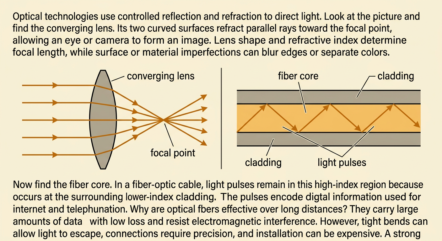
Optical technologies control light through reflection and refraction. A converging lens uses two curved refracting surfaces to bend parallel rays toward a focal point, allowing cameras and eyes to form images. Lens shape and refractive index determine focal length, while imperfections can cause blurred edges or color separation. Fiber-optic cables use total internal reflection to carry light pulses through a high-index core surrounded by lower-index cladding. The pulses encode digital information for internet and telephone communication. Fiber optics can transmit large amounts of data over long distances and resist electromagnetic interference. However, fibers can lose signals at tight bends, require careful connections, and may be costly to install. A strong technical explanation should connect evidence, such as measured refractive indices and critical angles, to device performance while also acknowledging these strengths and limitations.