
Rotational Motion, Torque, and Angular Momentum
Students connect torque and moment of inertia to angular acceleration and use conservation of angular momentum to explain rotating systems.
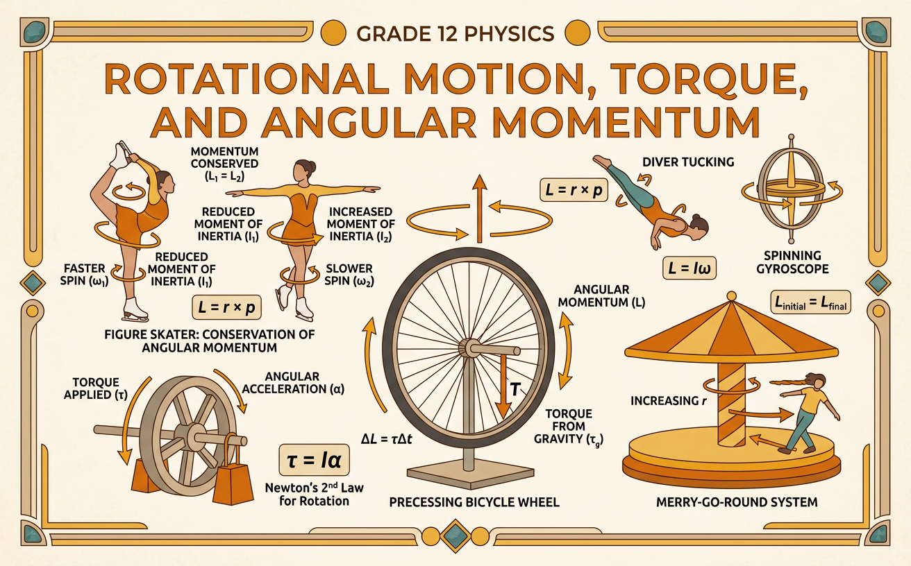
Illustrations are auto-generated and may be placeholders. They can be refreshed to match the narration.
Angular Position and Velocity
Angular position describes an object’s orientation relative to a chosen reference line. It is represented by theta and is usually measured in radians, where one complete revolution equals 2 pi radians. Angular velocity, omega, is the rate at which angular position changes: average omega equals change in theta divided by change in time. On an angular position-versus-time graph, angular velocity is the slope. Every point on a rigid rotating object has the same angular velocity, but points farther from the axis have greater tangential speed because v equals r times omega. For example, a bicycle wheel rotating at 2 revolutions per second has an angular velocity of 4 pi radians per second. If its radius is 0.50 meter, a point on the tire moves at about 6.28 meters per second.

Torque and Lever Arms
Torque measures how effectively a force causes rotation about an axis. Its magnitude is tau equals r F sine phi, where r is the distance from the axis to the point of application and phi is the angle between the position vector and the force. An equivalent calculation is tau equals F times the perpendicular lever arm. A force applied farther from the axis or more nearly perpendicular to the radius produces greater torque. Torque is measured in newton-meters, and its sign identifies clockwise or counterclockwise rotation. For example, an 80-newton force applied perpendicular to the end of a 0.25-meter wrench produces 20 newton-meters of torque. If the same force is applied at 30 degrees to the wrench, the torque is only 10 newton-meters because only the perpendicular force component causes rotation.

Moment of Inertia
Moment of inertia describes an object’s resistance to changes in rotational motion. It depends on both total mass and how that mass is distributed relative to the axis. For point masses, I equals the sum of m r squared, so moving mass farther from the axis greatly increases rotational inertia. Its SI unit is kilogram-meter squared. Shape also matters: a uniform solid disk rotating about its center has I equals one-half M R squared, while a thin hoop of the same mass and radius has I equals M R squared. Therefore, the hoop is harder to start or stop. For example, if a disk and hoop each have a mass of 4 kilograms and a radius of 0.50 meter, their moments of inertia are 0.50 and 1.00 kilogram-meter squared, respectively. The hoop requires twice the torque for the same angular acceleration.

Newton’s Second Law for Rotation
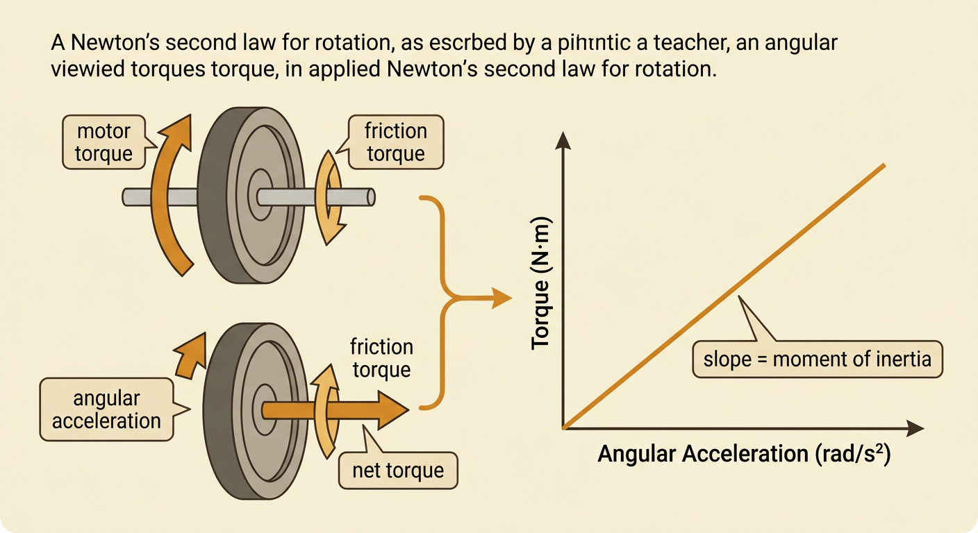
Newton’s second law for rotation states that the net external torque on an object equals its moment of inertia times its angular acceleration: net tau equals I alpha. Angular acceleration, alpha, is the rate of change of angular velocity. This relationship parallels the linear equation net force equals mass times acceleration. For a fixed moment of inertia, a graph of net torque against angular acceleration is a straight line whose slope is I. For example, suppose a wheel has a moment of inertia of 0.50 kilogram-meter squared. If the net torque is 3.0 newton-meters, its angular acceleration is 6.0 radians per second squared. Opposing friction torque must be included when finding net torque. If a motor provides 4.0 newton-meters while friction provides 1.0 newton-meter in the opposite direction, the net torque is still 3.0 newton-meters.
Conservation of Angular Momentum
Angular momentum measures rotational motion. For a rigid object rotating about a fixed axis, L equals I omega. The total angular momentum of a system remains constant when the net external torque is zero. Internal forces may redistribute mass and change the moment of inertia, but they do not change the system’s total angular momentum. Therefore, if I decreases, omega must increase so that their product remains constant. A spinning figure skater demonstrates this relationship. Suppose the skater’s moment of inertia is 4.0 kilogram-meter squared with arms extended and the angular velocity is 2.0 radians per second. The angular momentum is 8.0 kilogram-meter squared per second. If pulling in the arms reduces the moment of inertia to 2.0 kilogram-meter squared, the angular velocity increases to 4.0 radians per second. Friction eventually slows the skater because it supplies an external torque.

Rotational Safety Applications
Rotational principles guide safety decisions for vehicles, tools, turbines, and other machines. A spinning object can store substantial rotational kinetic energy, K equals one-half I omega squared, and its angular momentum prevents it from stopping instantly. Brakes must apply an opposing torque over time, while guards help contain fragments if a rotating part fails. For example, a grinding wheel with a moment of inertia of 0.20 kilogram-meter squared rotating at 100 radians per second stores 1,000 joules of rotational energy. A safety guard and an interlock that prevents access until the wheel slows can reduce injury risk. Engineers can evaluate the design by measuring stopping time at different braking torques and inspecting failure tests. An evidence-based safety argument should combine these data with calculations, diagrams, and limits of the model, such as friction changes or uneven mass distribution, before recommending regulations or equipment standards.
