Route a Message Through a Computer Network
Students model how digital messages travel through a network, test multiple routes, and improve the network when a connection fails.

Illustrations are auto-generated and may be placeholders. They can be refreshed to match the narration.
Meet the Network Nodes
A computer network is a group of connected devices that can share information. Each device or connection point is called a node. Computers, tablets, printers, servers, and routers can all be nodes. Lines between nodes represent connections that carry data. For example, imagine a classroom network with a tablet, two routers, and a server. The tablet sends a request for a science webpage. A router receives the request and passes it toward the server. Each node has a different job, but the nodes work together. In a classroom model, students can stand in labeled spots as nodes and hold yarn to show connections. A useful network needs both nodes and working connections between them.

Send a Message Packet
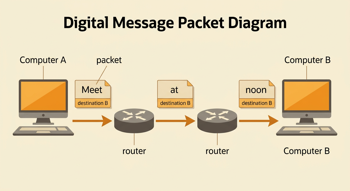
Digital messages are divided into small pieces called packets. A packet contains part of the message plus information about where it should go. Network devices read the destination information and forward the packet to the next node. Suppose Mia sends the message “Meet at noon” from Computer A to Computer B. The class can model the message with three cards labeled “Meet,” “at,” and “noon.” Each card also lists Computer B as its destination. Students acting as routers pass the cards along the network. Packets may travel separately, but the receiving computer puts them back in order. To test the model fairly, use the same starting node, destination, message cards, and passing rules during every trial.
Compare Possible Routes
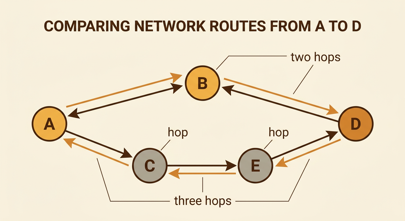
A route is the path a packet follows through a network. One network may offer several routes between the same two devices. For example, a packet could travel from A to B to D, or from A to C to E to D. Count each connection the packet crosses as one hop. The first route has two hops, while the second has three. Students can compare routes by sending the same packet from A to D and recording the number of hops or the delivery time. Keep the packet, start, destination, passing speed, and network layout the same so the test is fair. A shorter route may be faster, but another route can be valuable if the shortest route becomes crowded or broken.
Test a Connection Failure
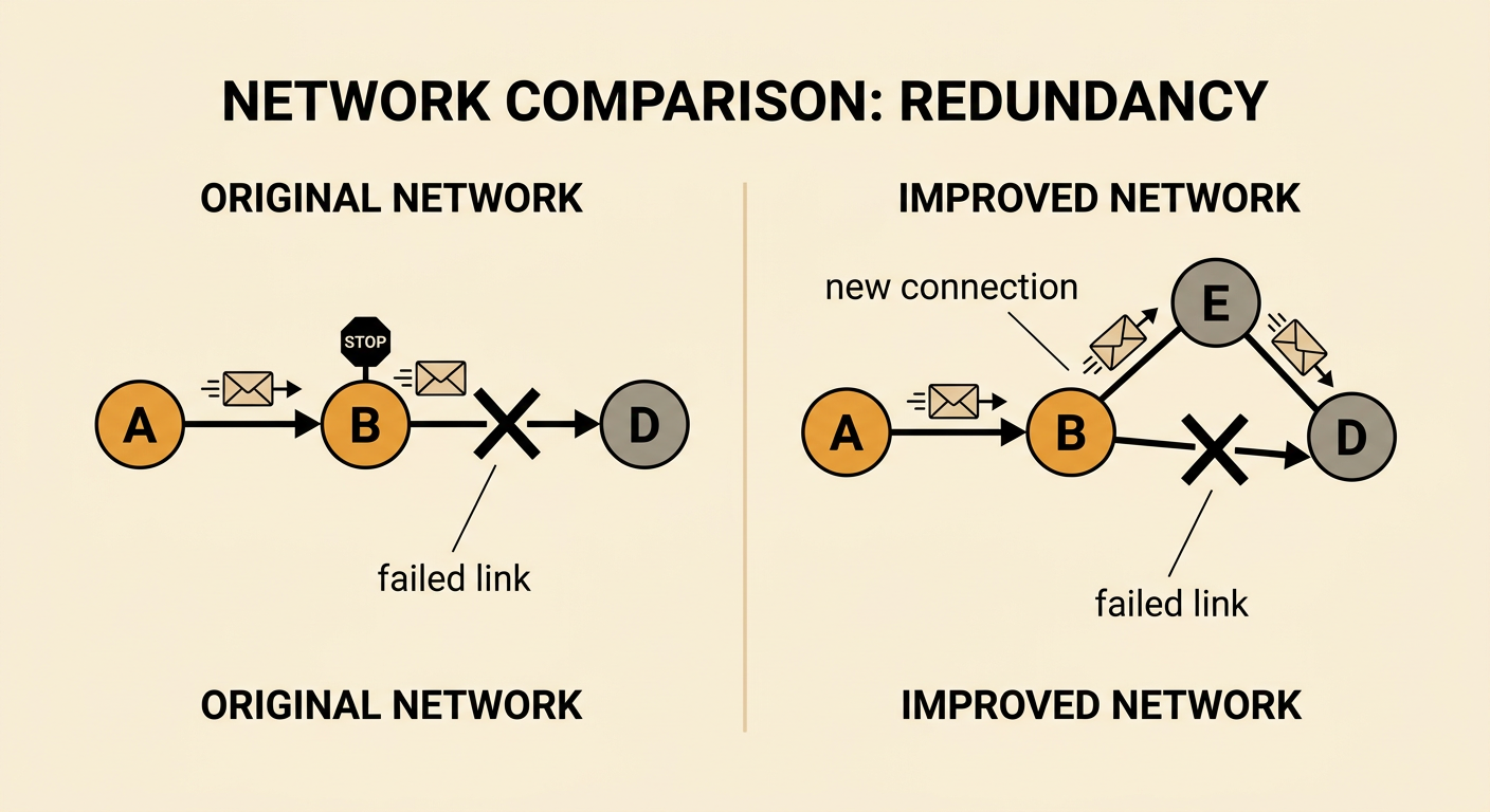
A connection failure happens when data cannot travel across one link. To study a failure point, first send a packet through the complete network and record whether it arrives. Next, block one connection, such as the link between B and D, with a “closed” card. Keep everything else the same: use the same packet, starting node, destination, network layout, and passing rules. Send the packet again. If the packet stops at B, the model has revealed a failure point. If another route exists, the packet can be redirected through different nodes. Repeat each trial several times and record the results. Changing only one connection at a time makes the comparison fair and shows which part of the network caused the problem.

Improve the Network Design
Engineers improve a network after studying test results. If one broken connection prevents delivery, the network may need another route. For example, suppose every packet from A stops when the B-to-D link fails. Students could add a connection from B to E, allowing packets to travel from A to B to E to D. Draw the improved design, predict what will happen, and test it under the same conditions as before. Use the same starting node, destination, packet, failed link, and passing rules. Record whether the packet arrives and how many hops it takes. A successful improvement delivers the packet even when the original link is unavailable. Engineers must also consider trade-offs because extra connections can increase cost and complexity while making a network more reliable.